Technical Information Note
Carbon Evaporation with rods versus threads
Introduction
Carbon coating is widely used in electron microscopy and related applications. The methods used for carbon coating are:
- Carbon evaporation in a low vacuum (LV) table top system
- Carbon evaporation in a high vacuum (HV) system
- Carbon evaporation with an Electron Beam carbon source
- Carbon sputtering with an Ion-Beam.
This application note covers carbon evaporation in low and high vacuum systems.E-Beam carbon evaporation and carbon sputtering are not covered in this application note.
E-Beam carbon coating uses carbon rods placed within a tungsten filament and is used for highest quality carbon coating (TEM, Freeze Fracture, Cryo).
Carbon sputtering is used in systems using an Ion-Beam for indirect sputtering from a carbon target. Reports on the quality and conductivity of this type of carbon coating are mixed; carbon seems to be deposited as a clear, non-conductive diamond like carbon (DLC).
Carbon coating is used for:
Support films for TEM (HV evaporation)
Conductive films on non-conductive sample for SEM/EDX (LV evaporation)
Conductive films on non-conductive microprobe samples (HV evaporation)
Conductive films for non-conductive FESEM samples (HV evaporation)
Conductive films for non-conductive FIB samples (HV evaporation)
Carbon rod evaporation
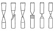
Carbon rods are normally used in a Bradley type evaporation source with shaped carbon rods. The features of carbon rod evaporation are:
- High purity carbon rods with small surface area reduce contamination
- Thickness can be easily controlled between 5-50nm from a single rod
- Control over power and evaporation time control thickness
- Clean carbon film
- Needs a higher rated power source (up to 200A)
- Multiple evaporation with a single set of rods is possible
Carbon fiber evaporation
Carbon fibers are used to make strands which are then braided into threads. The finished braided threads are thermally threated to reduce the amounts of impurities. The features of carbon fiber evaporation are:
- High surface area of carbon fibers increase chance of contamination
- Thickness controlled by diameter of thread
- Flash evaporation is mostly used
- Carbon fibers tend to “rain down” on the sample surface
- Smaller power supply is sufficient; typically 50A
- Source needs reloading after each evaporation
Conclusion
Considering the above mentioned differences, it is clear that carbon rod evaporation not only gives better control over the thickness, but also delivers a higher quality carbon film without contamination and debris.
Note 1: Quality of carbon coating.
Carbon evaporated in low vacuum (<10-3 mbar using a rotary pump) tends to have a more crystalline structure which becomes visible at magnifications of 25,000 – 35,000x. This type of coating is sufficient for most SEM/EDX applications.
Carbon evaporated in high vacuum (>10-5 mbar using a turbo pump and a backing pump) appears to be virtually amorphous and has a conductivity which is about 10x better than when evaporated in low vacuum.
Note 2: Use of a shutter.
Some systems using carbon fiber are equipped with a shutter and the sample is not positioned directly under the carbon source. This will decrease debris, both is only suited for very thin layers
Note 3: Debris.
Some systems using carbon fiber have a more precise control over the power supply and use thicker fiber threads; they have better control over the thickness. However, contamination and debris are still a contingency.
Note 4: Avoid carbon and Gold in a single chamber.
Avoid using a carbon coater with both Au sputtering and carbon evaporation in a small chamber. The carbon evaporation tends to contain Au dust in the layer due to cross contamination.
Note 5: Carbon coating for EDS and BE imaging.
Carbon coating is preferred for X-ray analysis and Backscattered Electron imaging. The low atomic number of carbon hardly interferes with X-rays used for EDS analysis and/or backscattered electrons used for atomic number contrast imaging.
Note 6: E-Beam carbon
Electron beam evaporated carbon (at 10-7 mbar) is stronger and films can be used at a thickness down to 2-3nm.

Possible shapes of shaped carbon rods for carbon rod evaporation. The last two versions on the right are usually preferred.


